Many scientific and artistic camera applications require precise exposure timing, such as when capturing the stroboscopic effect, performing stereo depth mapping, or imaging with TIRF microscopy1. This can be achieved even with the Raspberry Pi HQ camera, though it took some work and reverse engineering to get there.
The Raspberry Pi HQ camera is a good option for tinkering as it supports C- and CS-mount optics, but the existing libraries make it difficult to quickly and accurately synchronize external hardware with camera captures. During my time at 454 Bio, we built an open-source and cost-effective TIRF microscope that worked around this, and used it to develop DNA sequencing chemistry. To achieve this, we needed to synchronize the TIRF LED flashes with the camera exposures.
Assumptions about the camera
The Raspberry Pi documentation suggests that the camera can act like a still camera, particularly with commands like rpicam-jpeg and rpicam-still. This slightly stretches the truth: while I was researching all of the available Pi camera implementations, the following from the picamera documentation stood out:
The notion that the camera is effectively idle until we tell it to capture a frame is also misleading. Don’t think of the camera as a still image camera. Think of it as a video camera. Specifically one that, as soon as it is initialized, is constantly streaming frames (or rather rows of frames) down the ribbon cable to the Pi for processing.
The camera can take several seconds to initialize with a given set of parameters (exposure time, brightness, contrast, etc.). After that, it captures and discards a few frames internally as it fills its buffer and waits for automatic gain and white balance to converge.
In our application, once the sequencing reaction is started by heating up the slide, there is no way to stop or slow it down. As a result, we need to be able to capture images as quickly as possible.
My conclusion from these competing requirements was that the user would need to pick a set of parameters prior to starting a sequencing run and never change it.
Camera as a trigger source
Raspberry Pi released support for the sync signals in a firmware update in 2020. In their announcement, the closest thing to proper still captures that they were willing to document was “trigger mode sync”:
It is possible to synchronise the readouts of two or more imx477 sensors by wiring their XVS test points together. These devices can be on separate Pi boards, or can be on a Compute Module (CM) board with two sensors attached.
One camera must act as a trigger source, and the others act as trigger sinks.
This wasn’t quite what we were hoping for, but simply knowing when the camera started its “exposure” is enough to be able to synchronize flashes with the sensor.
Electronics
This isn’t quite plug and play as XVS still needs to be connected to GPIO on the Pi.
To do this, first solder wires onto the GND and XVS pads on the camera module:2
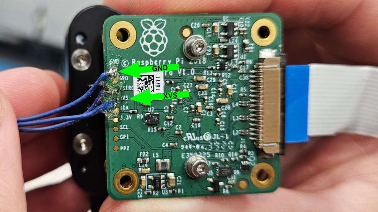
XVS is at a 1.8v logic level, and the Pi’s GPIO pins are at a 3.3v logic level. You can use an off-the-shelf level shifter3, like this one from SparkFun or a dupe of it on Amazon, along with some resistors to create a voltage divider for the 1.8v reference voltage on the LV pin.2
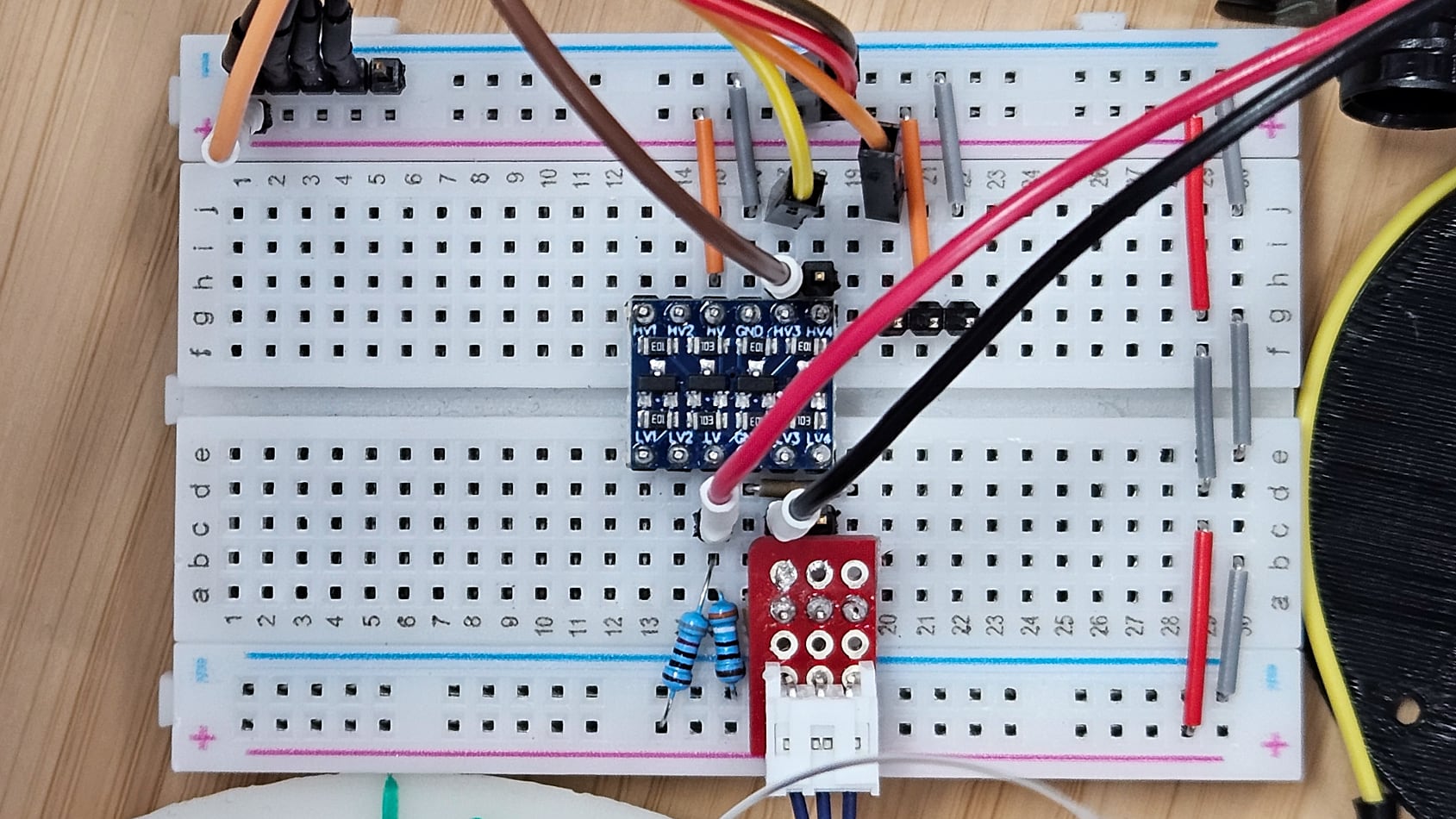
As pictured, the camera’s XVS and GND go to LV3 and a common GND. HV goes to one of the 3.3v pins on the Pi and HV3 goes to GPIO pin 6.
Configuration
Then, the Pi will need to be configured to use XVS as an output (i.e. a trigger source) by appending imx477.trigger_mode=1 to your /boot/cmdline.txt.
On a typical Pi, a complete /boot/cmdline.txt contains something along the lines of the following:
console=serial0,115200 console=tty1 root=PARTUUID=6699147f-02 rootfstype=ext4 fsck.repair=yes rootwait quiet splash plymouth.ignore-serial-consoles imx477.trigger_mode=1
Then reboot, and whenever the camera is initialized, you should be able to detect pulses on GPIO pin 6 whenever the sensor starts or stops an exposure.
XVS signal timing and Raspberry Pi-based interrupts
I naively tried to read the XVS signal a few ways — first by polling, and later with pigpiod’s callback function. Nothing seemed to work, so I connected XVS to a Saleae logic analyzer to try to figure out what was going on. After lots of zooming in, I could see the pulse but it was only 30 ns long:
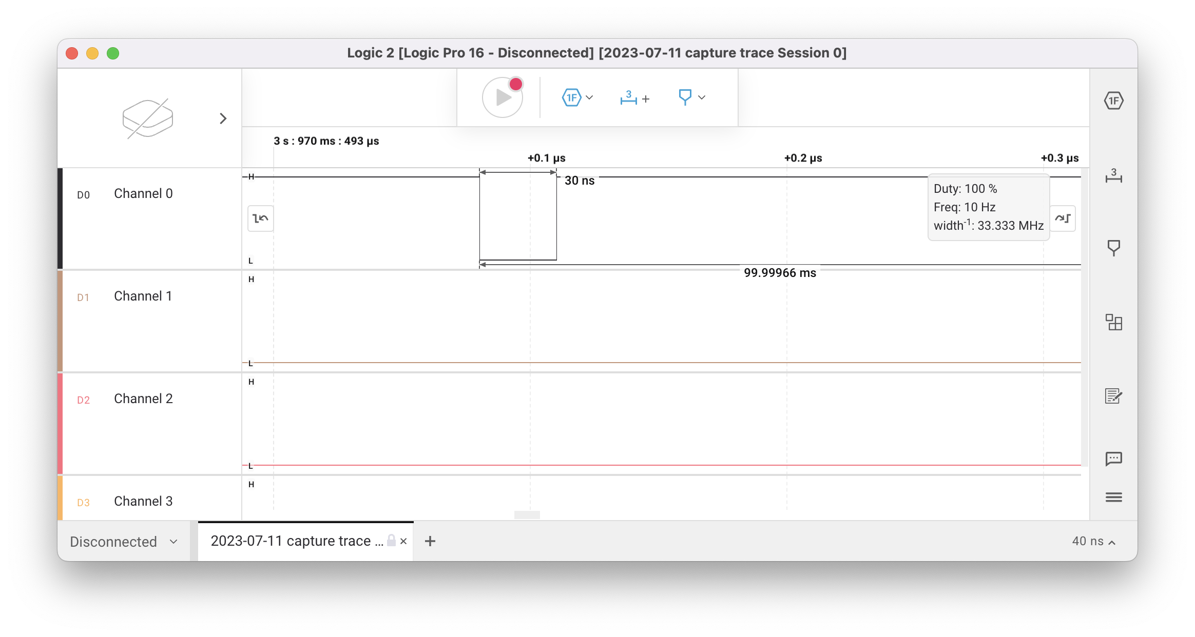
pigpiod’s documentation made it very clear that it was only capable of detecting pulses 1 µs or longer:
The GPIO are sampled at a rate set when the pigpio daemon is started (default 5 us).
The number of samples per second is given in the following table.
              samples
              per sec

         1  1,000,000
         2    500,000
sample   4    250,000
rate     5    200,000
(us)     8    125,000
        10    100,000
I pored through the Raspberry Pi documentation to see if there was a way to increase the pulse duration, but the one method I found (setting imx477_vsync_width in /boot/config.txt) only worked on 32-bit Raspbian and we were not willing to downgrade for a variety of reasons.
Because the pulse is so short, the most sensible approach is to treat the Pi like a microcontroller and use a hardware interrupt.4 On Raspbian Buster, the only way that Linux exposes these is with the deprecated sysfs GPIO interface, which pigpio (but not pigpiod) exposes via the gpioSetISRFunc function.
First, make sure that pigpio is initialized, set the pin as an input, and register the callback:5
#include <array>
#include <system_error>
#include <pigpio.h>

constexpr static unsigned int XVS_PIN = 6;
constexpr static std::array<unsigned int, 4> LED_PINS {16, 17, 20, 21};

void xvs_callback(int user_gpio, int level, uint32_t tick);

// Optional, but helpful:
// Converts rc-style errors into exceptions.
inline void CHECK_RC(int rc, const std::string &hint)
{
    if (rc < 0)
    {
        throw std::system_error(std::make_error_code(static_cast<std::errc>(rc)), hint);
    }
}

int main(int argc, char **argv)
{
    CHECK_RC(gpioInitialise(), "Could not initialize GPIO");
    CHECK_RC(gpioSetMode(XVS_PIN, PI_INPUT), "Could not set up XVS input");
    CHECK_RC(gpioSetISRFunc(XVS_PIN, FALLING_EDGE, 0 /*timeout*/, xvs_callback), "Could not set up shutter callback");
    for (unsigned int pin : LED_PINS)
    {
        CHECK_RC(gpioSetMode(pin, PI_OUTPUT), "Could not set up LED pin");
        CHECK_RC(gpioWrite(pin, false), "Could not turn off LED");
    }

    // Callbacks are only valid as long as the process stays alive.
    CHECK_RC(gpioSleep(PI_TIME_RELATIVE, 10, 0), "");

    return 0;
}
Then define a callback appropriate for your application:
inline static size_t g_pulse_index = 0;

void xvs_callback(int user_gpio, int level, uint32_t tick)
{
    switch (g_pulse_index)
    {
        case 0:
        {
            // Red
            CHECK_RC(gpioWrite(LED_PINS[0], true), "");
            CHECK_RC(gpioDelay(50000), "");
            CHECK_RC(gpioWrite(LED_PINS[0], false), "");
            break;
        }
        case 4:
        {
            // Orange
            CHECK_RC(gpioWrite(LED_PINS[1], true), "");
            CHECK_RC(gpioDelay(50000), "");
            CHECK_RC(gpioWrite(LED_PINS[1], false), "");
            break;
        }
        case 6:
        {
            // Green
            CHECK_RC(gpioWrite(LED_PINS[2], true), "");
            CHECK_RC(gpioDelay(150000), "");
            CHECK_RC(gpioWrite(LED_PINS[2], false), "");
            break;
        }
        case 8:
        {
            // Blue
            CHECK_RC(gpioWrite(LED_PINS[3], true), "");
            CHECK_RC(gpioDelay(150000), "");
            CHECK_RC(gpioWrite(LED_PINS[3], false), "");
            break;
        }
        default:
        break;
    }

    ++g_pulse_index;
}
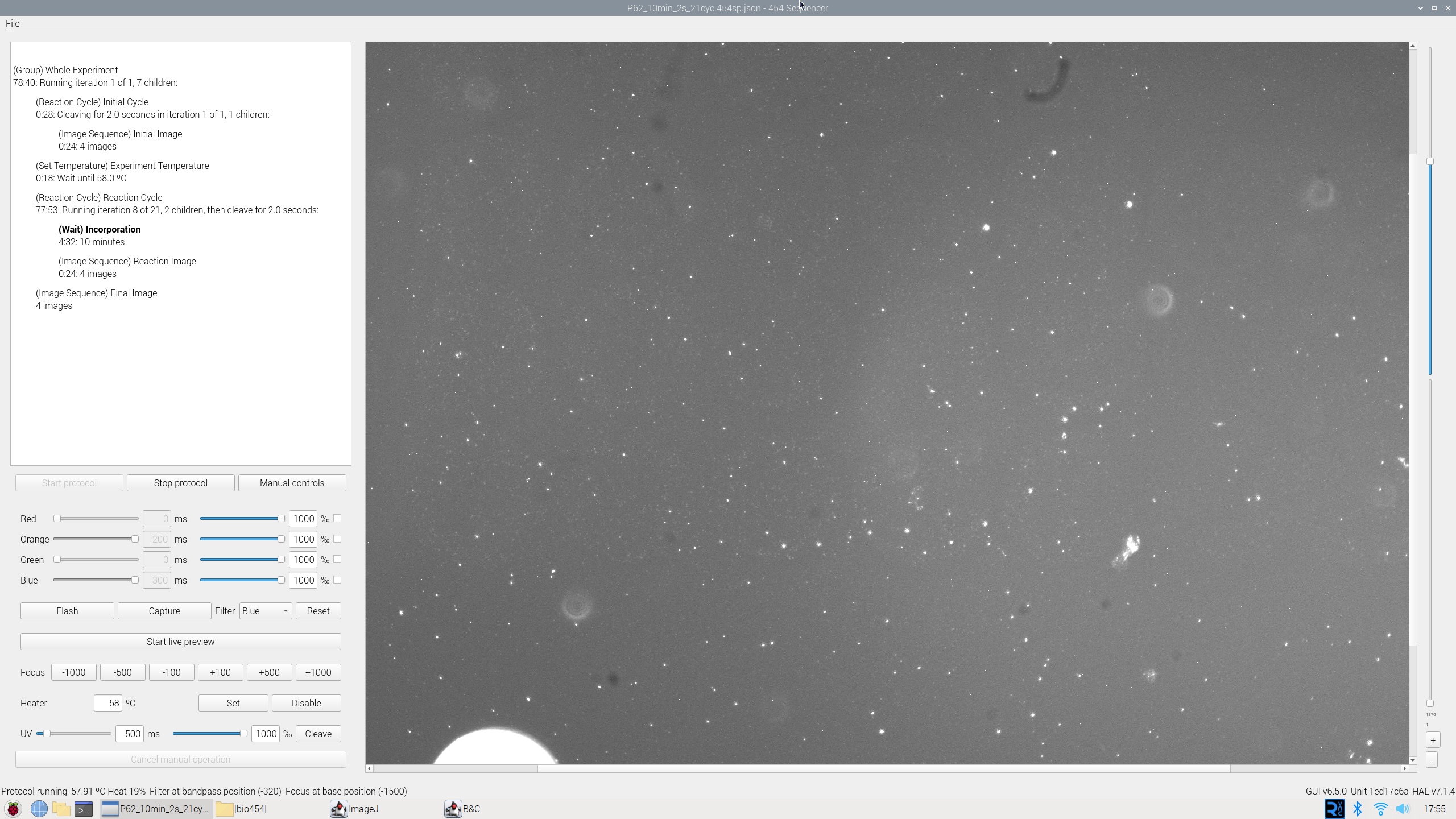
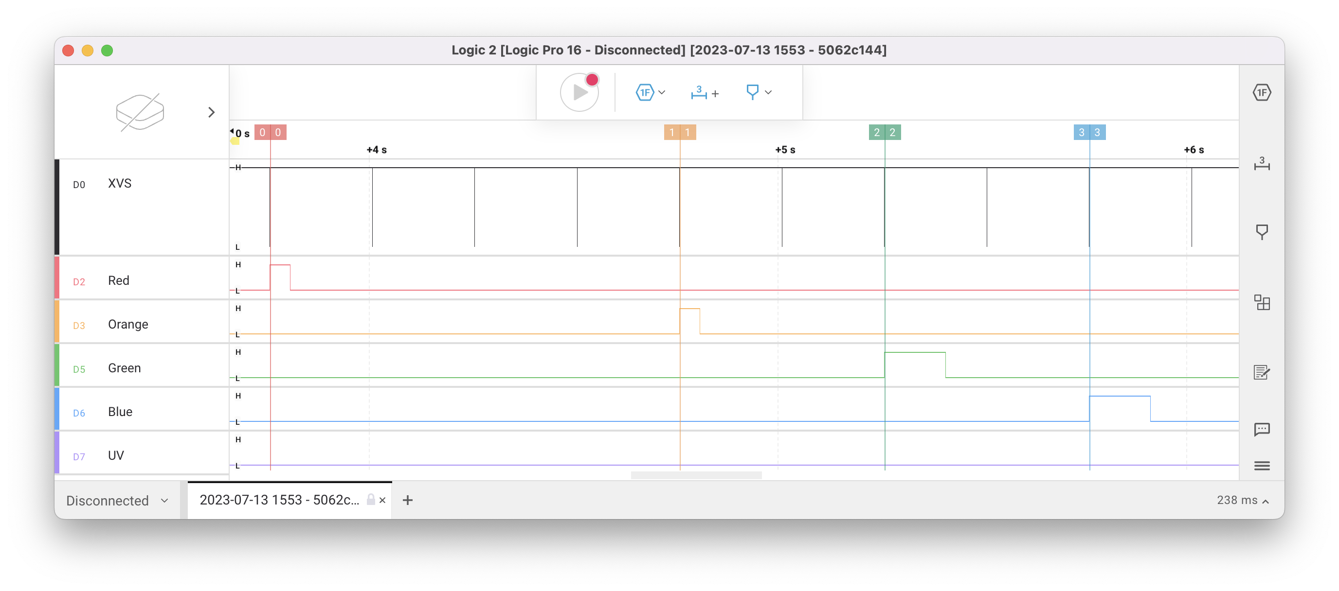
With all of this implemented, it was possible to synchronize the TIRF LED flashes with the start of each frame:
454 has since moved to a different software design for the Pi camera, so the closest surviving example of GPIO-based interrupts in 454’s code is in the pylablib camera controller used for purpose-built microscope cameras. This example expects the camera to be controlled by a different process (perhaps one of the libcamera-apps/rpicam-apps binaries) with an exposure duration of 250ms and has been greatly simplified to highlight the GPIO calls.
Exposure timing
Most digital camera sensors suffer from some sort of rolling shutter, and the Raspberry Pi HQ camera is no exception. While testing, I noticed that the image was dark at the top, suggesting that the flash started before all of the lines have begun exposing:

I conducted an experiment where I artificially added a delay between when our code received the XVS pulse and when it turned on the LED, and varied it between 0 and 100 ms. If the pulse was too late, the image would be dark at the bottom:

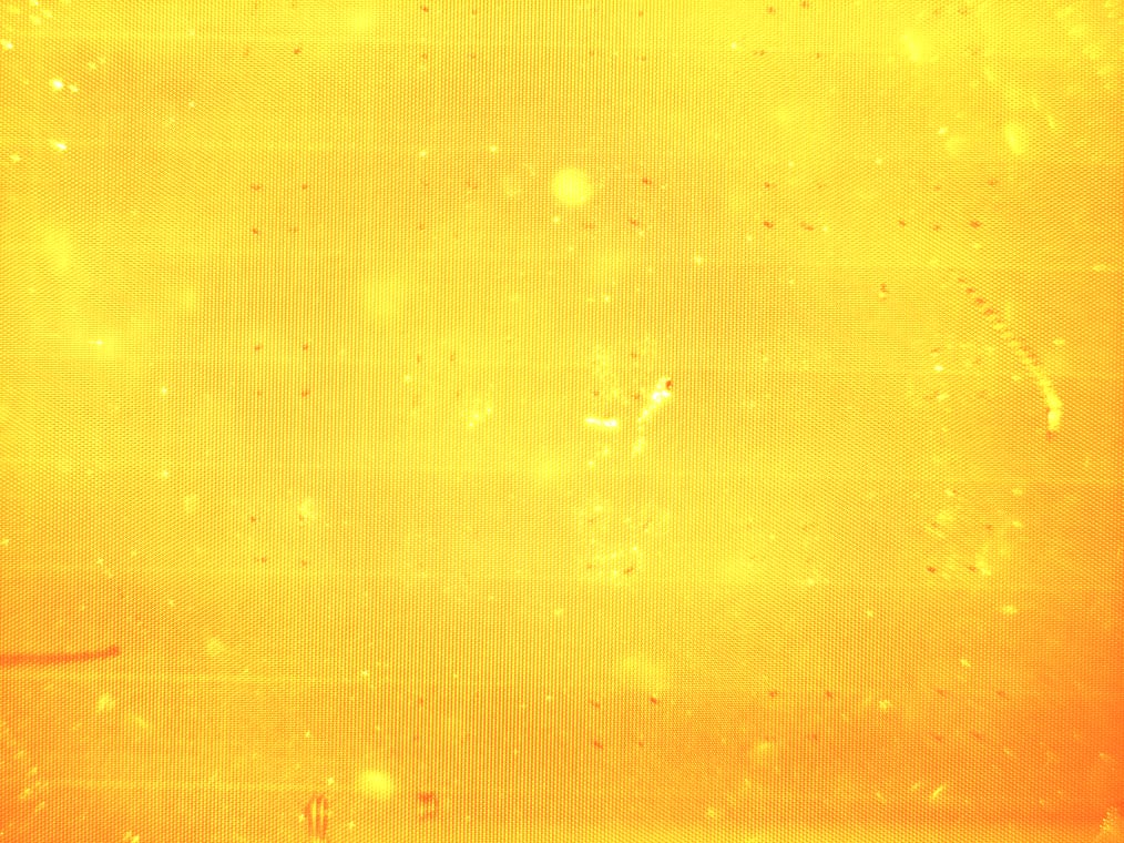
The “correct” value seemed to be 85 ms, which uniformly illuminated the entire slide:
Gotchas
If your application is for scientific data collection, as was the case with 454’s DNA sequencer, you should disable camera features like automatic gain control and white balance. These will make the data unreliable as the pixel intensity values cannot be compared between images. To do this, edit the config.txt used by libcamera-*/rpicam-*6 so that all of its values are fixed:
brightness=0.0
contrast=0.0
saturation=1.0
sharpness=1.0
awb=custom
awbgains=0,0
exposure=normal
shutter=250000
ev=0
denoise=off
gain=8.0
vflip=true
hflip=false
Earlier, I wrote:
you should be able to detect pulses on GPIO pin 6 whenever the sensor starts or stops an exposure.
Using this technique, there is no direct way to tell whether the pulse indicates the start or the stop of the exposure. If this program is started before the camera is initialized, you can count the pulses: odd pulses indicate the exposure is starting and even pulses indicate it is stopping.
It may be instead be easier to have your software act as the source of XVS pulses, rather than as the sink. For this and other reasons, this is the architecture I landed on with 454, and will be discussed in a future article.
-
Image from 454 Bio documentation, used under the terms of CC BY-SA 4.0. ↩︎
-
Image and text adapted from 454 Bio documentation, used under the terms of CC BY-SA 4.0. ↩︎ ↩︎
-
I recommend using a bidirectional level shifter to avoid having to redo any wiring if you decide to use XVS as an input, as will be described in a future article. ↩︎
-
Yes, it may have been easier at this point to just use an Arduino for the interrupt and LED control, but as usual I was convinced that additional hardware wasn’t necessary. ↩︎
-
Code adapted from 454 Bio
tirf-hal, used under the terms of the AGPL. ↩︎ -
I modeled 454’s
tirf-halcamera controller afterrpicam-appsso it accepts the same format. The implementation of this can be seen inPiCamera::connect_camera. ↩︎